Isometric Drawing Symbols For Piping
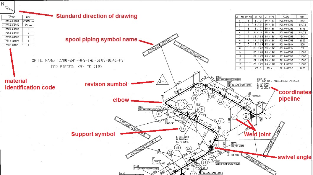
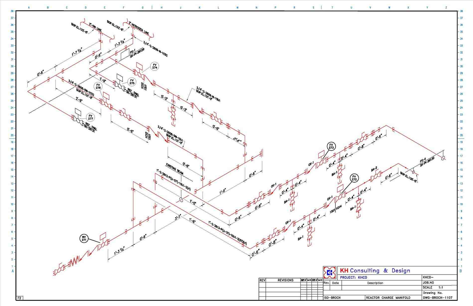
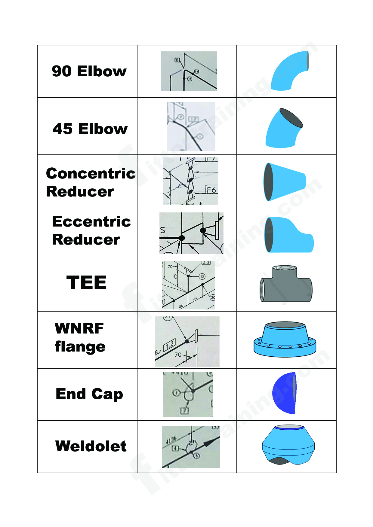
Isometric Drawing Symbols For Piping - Web mechanical symbols for isometric drawings. Isometrics are usually drawn from information found on a plan and elevation views. Reference number of pefs (p&id), ga drawings, line numbers, the direction of flow, and insulation tracing. Lighter lines show connected pipe, and are not parts of the symbols. Web piping isometric drawings are detailed technical illustrations that show a 3d view of piping systems. The drawing axes of the isometrics intersect at an angle of 60°. Symbols for pumps, heat exchanger, pressure vessel, valves,and instruments etc. Structural reference points that provide location can be shown on isometric. Web location and direction help to properly orient the isometric drawing. Specifies the ratio of the drawing’s size to the actual size of the components. Three main rules in isometric drawing. Web the following information must be included in piping isometric drawings: Web a piping isometric drawing is a technical drawing that depicts a pipe spool or a complete pipeline using an isometric representation. Checkout list of such symbols given below. Web isometric drawing symbols for piping valves. The inception of isometric drawings, also known as piping isometrics, marks a crucial milestone in the world of engineering. Knowing legends and symbols that are universal for reading a piping isometric drawing is much helpful to gain info about the piping material or piping fittings that are going to be used for fabrication or construction work. Piping fabrication work is based on isometric drawings. 1.2 this set of standard symbols is intended for use on piping system diagrammatics and arrangements for ships. Fittings, flanges, and valves play essential roles in pipeline isometric drawings, each with unique symbols according to iso standards. 1.2 this set of standard symbols is intended for use on piping system diagrammatics and arrangements for ships. Web location and direction help to properly orient the isometric drawing. Web the following information must be included in piping isometric drawings: Unlike orthographics, piping isometrics allow the pipe to be drawn in a manner by which the length, width and depth. Piping fabrication work is based on isometric drawings. Discover the essentials of piping isometrics, including how they simplify complex piping systems for construction, maintenance, and documentation purposes. These highly structured drawings provide a comprehensive 3d representation of the arrangement, dimensions, and connections of pipes within a system. How does one identify isometric views? Web isometric symbols for piping fittings. In this dwg file you will find a huge collection of pipeline isometric drawings which are created in 2d format. Structural reference points that provide location can be shown on isometric. It is the most important deliverable of piping engineering department. 1.2 this set of standard symbols is intended for use on piping system diagrammatics and arrangements for ships. Checkout. Specifies the ratio of the drawing’s size to the actual size of the components. Web piping symbols for isometric drawings. Structural reference points that provide location can be shown on isometric. Unlike orthographics, piping isometrics allow the pipe to be drawn in a manner by which the length, width and depth are shown in a single view. Web how to. Web isometric symbols for piping fittings. Web various symbols are used to indicate piping components, instrumentation, equipments in engineering drawings such as piping and instrumentation diagram (p&id), isometric drawings, plot plan, equipment layout, welding drawings etc. Specifies the ratio of the drawing’s size to the actual size of the components. Web piping isometric dwg symbols designed just for you in. The inception of isometric drawings, also known as piping isometrics, marks a crucial milestone in the world of engineering. Web master piping isometrics with our comprehensive guide: Piping fabrication work is based on isometric drawings. Web an isometric drawing (or “iso”) is a pictorial view of one pipe, using isometric projection conventions to present a 2d view of a 3d. Web piping symbols for isometric drawings. How does one identify isometric views? Learn about p&id and pfd drawing symbols and legend used in oil & gas piping. Specifies the ratio of the drawing’s size to the actual size of the components. What is an isometric ? Specifies the ratio of the drawing’s size to the actual size of the components. Lighter lines show connected pipe, and are not parts of the symbols. Web piping isometric drawing software is an essential tool for piping engineers and designers to create detailed isometric drawings of piping systems. The symbols that represent fittings, valves and flanges are modified to adapt. These highly structured drawings provide a comprehensive 3d representation of the arrangement, dimensions, and connections of pipes within a system. These tools generate the 3d representation of the piping layout, including pipe dimensions, fittings,. Web how to read piping isometric drawing symbols. The inception of isometric drawings, also known as piping isometrics, marks a crucial milestone in the world of. Piping fabrication work is based on isometric drawings. The drawing axes of the isometrics intersect at an angle of 60°. In this dwg file you will find a huge collection of pipeline isometric drawings which are created in 2d format. Symbols for pumps, heat exchanger, pressure vessel, valves,and instruments etc. Unlike orthographics, piping isometrics allow the pipe to be drawn. Web table of content. Structural reference points that provide location can be shown on isometric. These tools generate the 3d representation of the piping layout, including pipe dimensions, fittings,. Knowing legends and symbols that are universal for reading a piping isometric drawing is much helpful to gain info about the piping material or piping fittings that are going to be used for fabrication or construction work. Web piping isometric drawing software is an essential tool for piping engineers and designers to create detailed isometric drawings of piping systems. Web piping symbols serve as the alphabet of isometric drawings, with each symbol representing a specific component, similar to words in a language. The inception of isometric drawings, also known as piping isometrics, marks a crucial milestone in the world of engineering. Web piping symbols for isometric drawings. Web isometric drawing symbols for piping valves. Three main rules in isometric drawing. Symbols are shown in black lines. Web an isometric drawing (or “iso”) is a pictorial view of one pipe, using isometric projection conventions to present a 2d view of a 3d pipe (fig. Reference number of pefs (p&id), ga drawings, line numbers, the direction of flow, and insulation tracing. It is the most important deliverable of piping engineering department. Reading tips, symbols, and drawing techniques for engineers and piping professionals. The symbols that represent fittings, valves and flanges are modified to adapt to the isometric grid.
What is Piping Isometric drawing? How to Read Piping Drawing? ALL
Piping Isometric Drawing Symbols Pdf at GetDrawings Free download
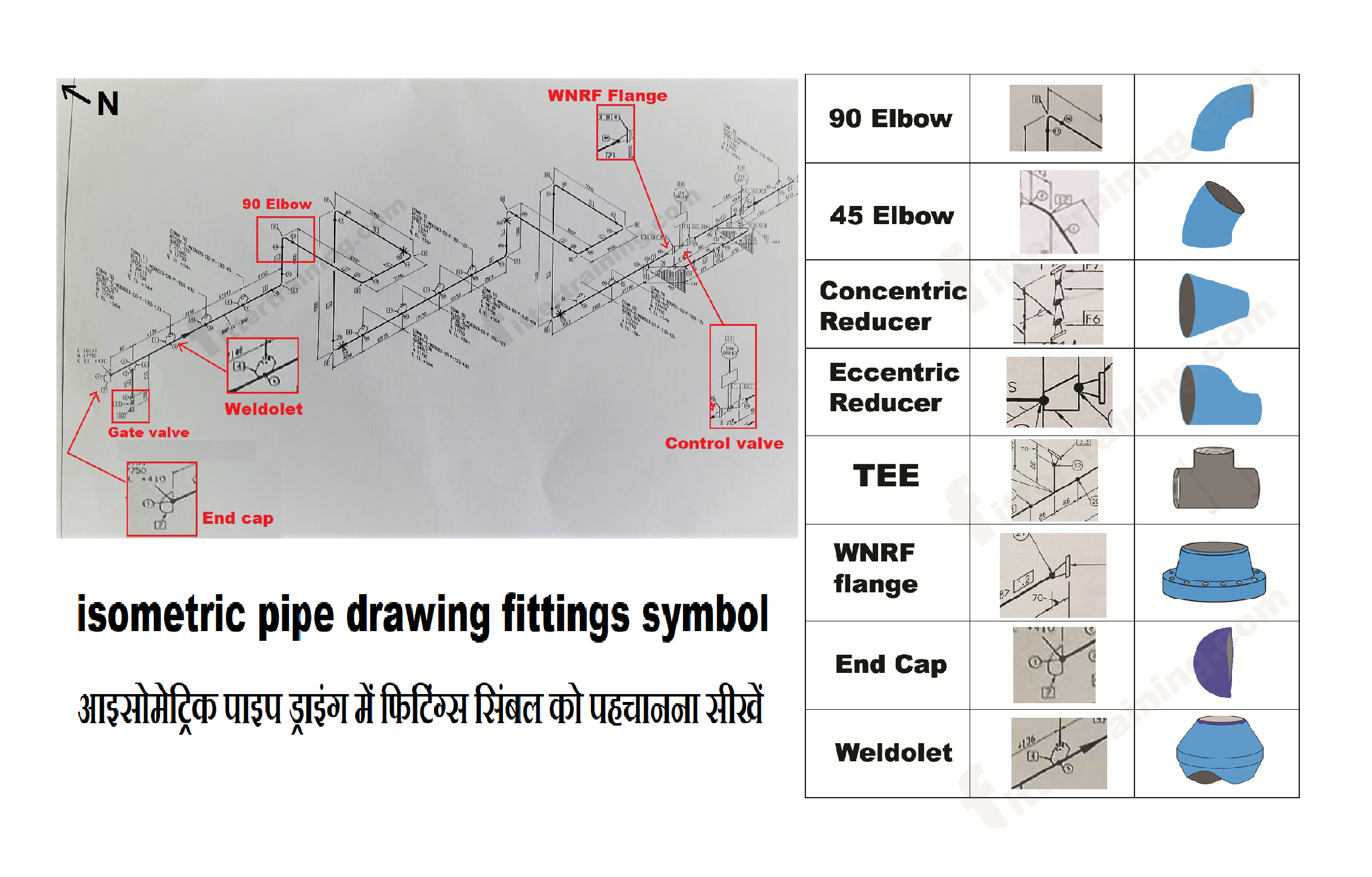
isometric pipe drawing fittings symbol Fitter training

Piping Isometric Drawings The Piping Engineering World
Piping Isometric Drawing Symbols Pdf at GetDrawings Free download

Piping Isometric DWG Symbols Free Download Drawing in CAD

Piping Isometric Drawing Symbols Pdf at Explore
Isometric Piping Drawing Symbols
Isometric drawing of piping bxestage

How to read isometric drawing piping dadver
Specifies The Ratio Of The Drawing’s Size To The Actual Size Of The Components.
Web Master Piping Isometrics With Our Comprehensive Guide:
Symbols For Pumps, Heat Exchanger, Pressure Vessel, Valves,And Instruments Etc.
Web Piping Isometric Drawings Are Detailed Technical Illustrations That Show A 3D View Of Piping Systems.
Related Post: